Search
Complete Guide to Building Your Brewery

$19.95 USD

Support our site by using these affiliate links
Control Panel (Part 2)
STEP 7: Wire up volt and amp meters
 The volt and amp meters are used to display the voltage being fed to the panel and the current consumption. Neither are truly required for the brewing operation. They simply give us piece of mind that things are operating as expected.
Our control panel is fed by a 30 amp circuit in our house. With everything running (including both pumps and one heating element) our current consumption is almost exactly 24 amps.
The voltage fluctuates throughout the year and based on the time of day. It's not uncommon to see the voltage sag (drop) by 5-8% during the hotter summer months when everyone is running their power hungry air conditioners. Voltage sags do not affect the brewing process.
Volt and amp meters display the voltage being fed to the panel and the current consumption:
Wire up the components as shown in the diagram below using the wire sizes and colours indicated. Make sure that the wire you use to connect to the AC inputs on the volt meter is rated to at least 240V. Most 4-conductor telephone station wire is rated to 300V which is perfect.
The doorbell transformers may include wiring that is slightly different than what is shown in the diagram below. Often the low voltage side will use screws as connection points instead of wires. If more than two connection points are available, the transformer offers more than one output voltage. In such cases connect wires to the two connection points that will supply approximately 16V. Connect the other ends of these two wires to the AC IN points on the power supply (polarity does not matter). If the transformer includes a green (ground) wire, connect it to the enclosure ground post or any other part of the control panel that is grounded, such as the back plate. Polarity of the high voltage side wires that connect to the HOT and NEUTRAL buses does not matter.
Using an adjustable power supply lets us adjust the brightness of the meters to match the rest of our lights. The location of the adjustment potentiometer is indicated by the yellow arrows in the wiring diagram (see below). Turn both counter clockwise for 20-30 revolutions to make sure the output voltage is initially set very low before using them for the first time, then slowly increase the voltage until the meter brightness matches the 120V blue power light. If you have a multimeter handy, we find that for our meters setting the power supply to around 4.5 - 4.7V DC output works best. Different brand meters may give different results, however, some may not run reliably under 5.0V DC. When in doubt, set to the output to 5.0V DC but no higher. Too high of a voltage may destroy the meters.
WARNING! Always confirm the connection points on the transformers, power supplies, and meters with the documentation that was supplied or by referring to the labels directly on the device itself. Your devices may use connections that are slightly different from the ones shown here. For example, do not assume that the left most connection on the back of the volt meter is for +5V DC. The manufacturer may have changed the pinout or you may have purchased a slightly different version than the one we use here. Always confirm and read the labels that are provided with the devices you install before attaching wires and turning on the power. Failure to do so can easily destroy the meters.
Volt and amp meter wiring diagram: 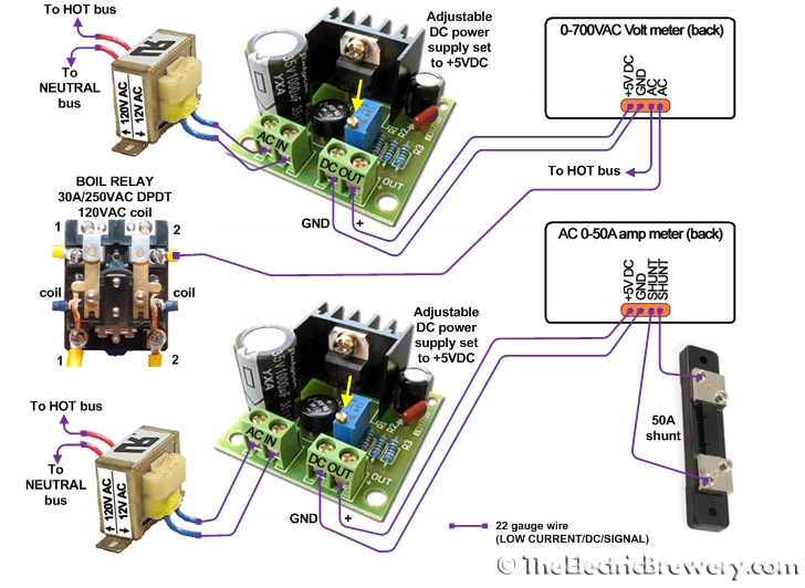
Meter labels will vary by manufacturer. Below are the meters we use with our control panels, with the connection points labelled to match those found in our wiring diagram:
For doorbell transformers that offer more than one output voltage, use the two connection points that offer 16V (the two rightmost screws in the picture below):![]()
How it works
 Both meters require 5 volts DC to operate. We use small 10:1 step-down transformers (doorbell transformers work perfectly) to take 120 volts AC down to 12 volts AC followed by small adjustable DC power supplies (AC 4V-30V input, DC 2.5V-27V output
![]() Because of the way this particular volt meter is designed (one of the AC inputs is tied to the DC ground), separate power supplies and transformers must be used in order to isolate the meters from each other. Trying to use one power supply and transformer to power both meters will destroy the meters (ask us how we know!) even through the supplied instructions say this is possible.
Because of the way this particular volt meter is designed (one of the AC inputs is tied to the DC ground), separate power supplies and transformers must be used in order to isolate the meters from each other. Trying to use one power supply and transformer to power both meters will destroy the meters (ask us how we know!) even through the supplied instructions say this is possible.
The volt meter can measure up to 700 volts AC and is connected directly across the two 120 volt AC lines (HOT A and HOT B) that produce a differential of 240 volts AC.
The amp meter can measure up to 50 amps AC. This large amount of current does not directly flow through the amp meter. Instead, a 50A shunt is used with a precisely known resistance (1.5 milliohms in our case). Current passes through the shunt and the amp meter measures the associated voltage drop (0.075V max) and translates it into amps. Amp meters and shunts are typically matched and sold in pairs.
The shunt is located immediately after the main power relay so that it measures all current that flows through the control panel.
Location of the components:
Close-ups:


