Search
Complete Guide to Building Your Brewery
$19.95 USD

Support our site by using these affiliate links
Control Panel (Part 2)
STEP 10: Wire up timer and alarms
Many steps during the brewing process are timed, from mashing the grains in the Mash/Lauter Tun (typically 60-90 minutes) to boiling wort in the Boil Kettle (typically 60-90 minutes).  During the boil hops are added at specific times to provide bitterness, flavour, and aroma. Adding hops at different times produces different results. It's all about timing.
Many brewers use inexpensive countdown kitchen timers to keep track of when these specific actions need to occur. We simply incorporated a timer directly into the control panel.
The Omega PTC-21 timer we use can be set to a maximum of 99 minutes and 99 seconds. The buttons labelled '4', '3', '2', and '1' are used to set the time. The (E)dit and (P)rogram buttons are used to program the unit when it is first installed. This is a one-time operation. (More on this later).
The top time (15:09) is the current time as it counts down, the bottom time (30:00) is the set time:
If the timer alarm switch is set to ON, the buzzer will sound once the timer reaches zero. The RESET pushbutton resets the timer back to the initial time to start counting down again.
We have it wired such that once the time is set it starts to count down immediately, so there is no need for a separate start/stop switch.
It's also not possible to 'pause' any of the brewing processes like mashing or boiling once they start, so the concept of being able to start/stop the timer is illogical in most brewing operations. After 2 years of use we've never found a reason to want one.
The alarm can be turned off by either switching the timer alarm switch to the OFF position, or by starting the countdown again by pressing the RESET pushbutton.
A countdown timer with RESET pushbutton is used to time the various brewing activities.
The timer alarm switch can be set to sound an alarm once the countdown reaches zero. 
Each of the PID controllers has two alarms built in and can raise an alarm if the temperature goes above one value or a below another. We use one alarm on/off selector switch per PID so that we can set the buzzer to sound if desired.
There are many ways that alarms can be used, some temperature based, some time based. The ones we use the most are:
- The hot liquor has reached strike temperature (alarm sent from the Hot Liquor Tank PID).
- The grain has reached a mash, step, or mashout temperature (alarm sent from the Mash/Lauter Tun PID).
- The mash is complete (alarm sent from the countdown timer).
- The hot liquor has reached sparge temperature (alarm sent from the Hot Liquor Tank PID).
- The wort is about to boil (alarm sent from the Boil Kettle PID).
- The boil is complete (alarm sent from the countdown timer).
- The wort has reached hop stand temperature (alarm sent from the Boil Kettle PID).
- The wort has reached yeast pitching temperature (alarm sent from the Boil Kettle PID). (Useful for brewers who use immersion chillers)
Each of the PID controllers has an alarm on/off selector switch: 
The alarm light turns on and the buzzer sounds if one of the four devices has its alarm switch 'ON' and an alarm state is reached:
Wire up the components as shown in the diagram below using the wire sizes and colours indicated.
Timer and alarm wiring diagram: 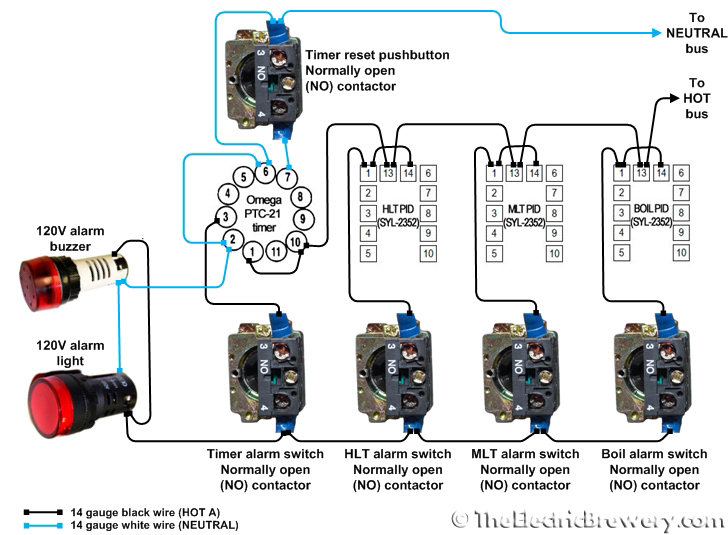
How it works
 While each of the PID controller temperature alarm values is programmed separately, the PID alarm outputs (together with the timer alarm output) are wired in parallel. It only takes one of the 4 devices to sound the alarm.
If any of the PID controllers or the timer raises an alarm state, an internal relay in the device is closed allowing power to flow to the 120V alarm buzzer and 120V alarm light as long as the respective alarm selector switch is also in the ON position.
The 4 alarm on/off selector switches are used to enable/disable the individual device alarms as desired. When all 4 are off, the 120V alarm buzzer will not sound and the 120V alarm light will not turn on.
Using separate alarm on/off switches makes it quick and easy to turn on or off a single alarm without affecting the others, and does not require us to reprogram the individual PIDs or timer alarm settings on every use. It provides the ultimate in flexibility and ease of use.
The timer terminals 6 (START) and 2 (NEUTRAL) are shorted and wired such that the timer starts counting down as soon as it is powered on.
If you are using a timer that is different than the Omega PTC-21, be aware that it will have different terminal connections and programming steps. You'll need to refer to your timer manual for wiring diagrams and programming instructions.
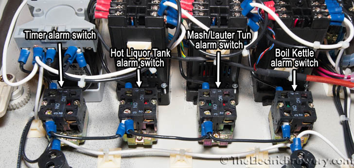
Location of the components:
Close-ups: