Search
Complete Guide to Building Your Brewery

$19.95 USD

Support our site by using these affiliate links
Control Panel (Part 2)
STEP 2: Build power cord
We need to build a power cord to get power from our dryer outlet in to the control panel.
Two options are available depending on where your GFCI is located:
- Use a cord with a 30A GFCI built in, or
- Use a standard 4-wire dryer cord (with a GFCI breaker in the electrical panel).
Regardless of the solution you choose, a GFCI should be used.
240V AC 30 amp cord with GFCI built in (17 feet long):
Standard 240V AC 30 amp dryer cord (10 feet long):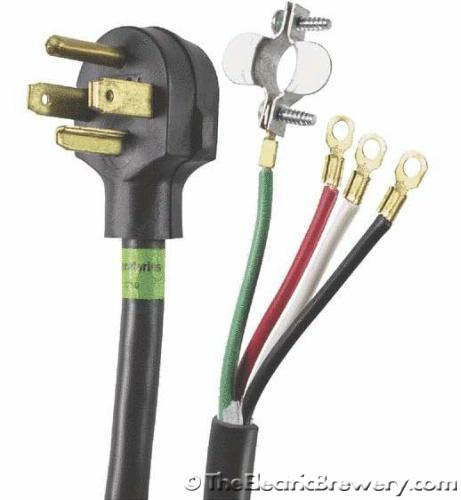
 Both cords are already equipped with a plug for plugging into our dryer outlet. All that's missing is the L14-30 connector on the other end to connect to our control panel.
If you use the 30A GFCI power cord be aware that it uses non-standard wire colours for HOT and NEUTRAL so be careful how you connect it up. Refer to the picture below and hook it up as follows to the L14-30 connector: The two hot wires (black and brown) are connected to the 'X' and 'Y' connectors with brass screws, the NEUTRAL wire (blue) to the 'W' connector with the silver screw, and the GROUND wire (green) to the 'G' connector with the green screw. Cut off any compression ring terminals first - all we need is bare wire.
If you use a standard 4-wire dryer cord the wire colours are typically standard. Refer to the picture below and hook it up as follows to the L14-30 connector: The two hot wires (black and red) are connected to the 'X' and 'Y' connectors with brass screws, the NEUTRAL wire (white) to the 'W' connector with the silver screw, and the GROUND wire (green) to the 'G' connector with the green screw. Cut off any compression ring terminals first - all we need is bare wire.
L14-30 connector used to connect to our control panel: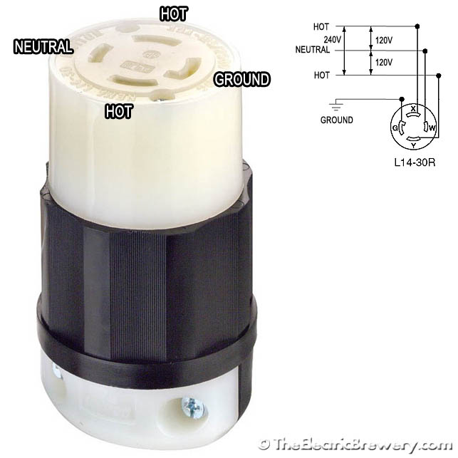
240V 30A power cord with GFCI built in, plugged in to the dryer outlet.
The actual GFCI circuitry is in the large grey box with the red 'test' and black 'reset' buttons.


