Search
Complete Guide to Building Your Brewery

$19.95 USD

Support our site by using these affiliate links
Control Panel (Part 2)
STEP 5: Wire up power
 A key operated selector switch is used to power the control panel. The control panel can only be powered up if the key is inserted and turned.
While a key operated switch is certainly not a requirement, it helps keep curious hands from being able to do any damage and also stops any unauthorized brewing. (Ok, that last one was a bit of a stretch).
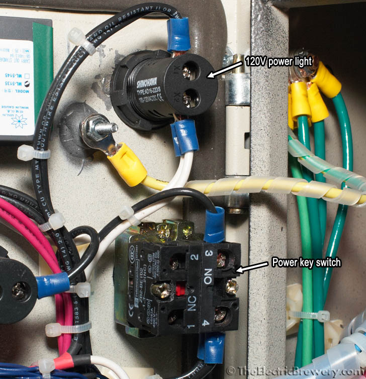
When the key power switch is turned to the on position, the blue LED pilot light turns on to let us know we have power.
The main control panel power switch requires a key. No unauthorized brewing!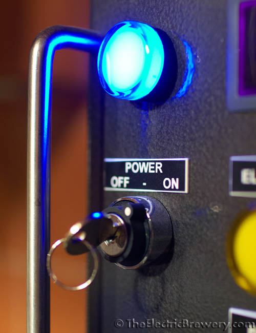
 Most small switches such as this one cannot handle the large amounts of current required by our system so current does not actually flow through the key operated power switch. Instead, the power switch is simply used to control a large relay which is capable of handling up to 30 amps. A relay is simply an electrically operated switch. Turning the power switch to the on position activates a coil in the relay which closes contacts able to handle up to the 30 amps of current we require. Current is then able to flow into the rest of the control panel to power the other devices including the high power devices like the heating elements.
Generally speaking, high power switching such as this is always controlled remotely in electrical panels where a smaller 'control' switch on the door is used to activate a larger switch (such as a high power relay or a definite purpose contactor) that is permanently installed on the back plate. This is done for ergonomic reasons (smaller switches are easier to operate) and for safety reasons (high power wires are not required to move or bend when the door is opened/closed).
Since this is the first wiring diagram, here are some hints:
- White (NEUTRAL) wires are shown as blue in our diagrams.
- When orientation is not important, it is not shown. For example, it does not matter which side of the 120V power light connects to the HOT or NEUTRAL bus nor does it matter which way wires are connected to the power key switch NO contactor or on which side of the switch the contactor is installed. In some cases orientation is extremely important: For example, The 14 gauge neutral wire must connect to the "W" (NEUTRAL) screw on the 30A/240V power in receptacle while the larger 10 gauge black wire must connect to the "Y" (HOT A) screw.
- You may notice what appears to be extra wires in some of the close-up photos when compared to the wiring diagrams. This is normal. For example, in the wiring diagram immediately below the 120V power light connects to the HOT and NEUTRAL bus only (2 wires, one black, one white) but in the photos further below there are 4 wires. This is because other parts that need to be wired to the HOT and NEUTRAL bus later on were wired to the two sides of the 120V power light instead. The result is the same. There's no need to send 10 pairs of wires all the way back to the buses each time.
- The HOT and NEUTRAL buses are simply connection points where multiple wires are tied together. In the power input wiring diagram below we show an example of how this can be accomplished. Which screws on the bus are used for the connections does not matter, but all wires connected to the bus must be tied together using short wire jumpers or pre-made terminal strip jumpers as the 8 small metal bars that make up the buses are not connected electrically. When connecting a wire, simply choose a free screw and then make a short wire jumper (or use pre-made terminal strip jumpers) to connect the new wire to the others on the bus. As mentioned in the previous bullet, if the component you wish to connect to a bus is close to another component that is already connected to the same bus through an existing wire, you may simply connect the two components together to save on wiring. In future wiring diagrams, these buses will not be shown in order to make the diagrams easier to read. Instead, we will simply indicate which bus a wire must connect to with an arrow and some text.
Wire up the components as shown in the diagram below using the wire sizes and colours indicated.
Power input wiring diagram: 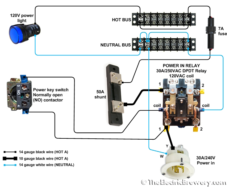
How it works
With the power key switch off, power is completely cut off from the rest of the control panel. Only the power switch itself is energized.
Turning the power key switch ON allows 120V to pass through the relay coil which closes the relay contacts (making a satisfying 'clunk' noise). This allows power from both the HOT A and HOT B lines to flow into the control panel. One HOT is used to energize the HOT bus which turns on the blue 120V power light.
We used a DPDT (double pole, double throw relay) which is essential two switches (poles) with two settings each (throws). We only use one of the throws in all our DPDT relays so DPST (double pole single throw) relays could also be used but are generally harder to find.
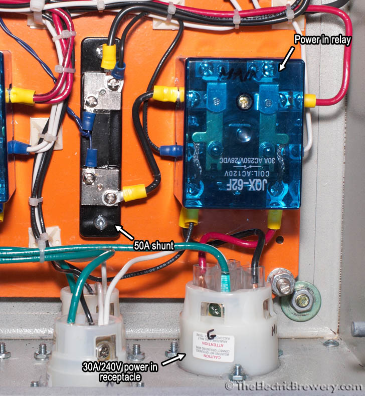
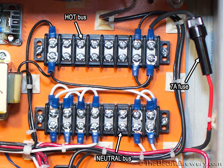
 The 30A breaker in our circuit breaker panel protects all 10 gauge wire right up to and inside our control panel. The 7A fuse in the in-line fuse holder is used to protect the smaller 14 gauge wire. Later on we'll be drawing power off the large 10 gauge wire before the fuse to run our power-hungry heating elements.
The 50A shunt is basically a large wire with a precisely known very low resistance (1.5 milliohms in our case). The amp meter measures the voltage drop across the shunt (0.075V max) to display the current used by our control panel. The tiny voltage drop does not affect the other equipment in the panel.
 Many of the lower power devices in the control panel are powered off the HOT (black) and NEUTRAL (white) wires so two 8 position terminal strips are used as common connection points (known as 'buses'). The 8 positions are not wired together by default so short jumper wires are used as shown in the diagram above. You may also use pre-made terminal strip jumpers. In future diagrams we will simply indicate when a wire must be connect to one of the two buses without showing the entire bus. It's up to you to create the short jumpers and make sure that all the HOT or NEUTRAL wires are joined together.
Location of the components: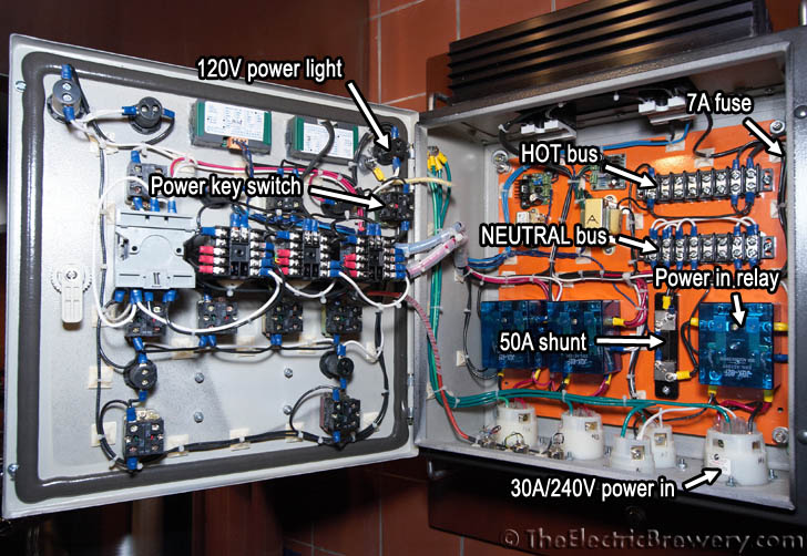
Close-ups: