Search
Complete Guide to Building Your Brewery

$19.95 USD

Support our site by using these affiliate links
Heating Elements
Electrical heating elements similar to those found in electric hot water tanks are used as heat sources in our brewery. Elements are installed in two of our 20 gallon Blichmann Boilermaker kettles: One in the Boil Kettle (used to boil wort) and another in the Hot Liquor Tank (used to heat strike and sparge water).
Sizing the element correctly is important: You want it large enough to be able to heat water fairly quickly and be able to maintain a good rolling boil in the Boil Kettle. A 5500W heating element is good for boiling around 8-20 gallons, perfect for our setup. If boiling less than 8 gallons, a 4500W heating element works well. If boiling more than 20 gallons, consider two 5500W elements.
 We use the Camco #02965 5500W 240VAC ultra low watt density (ULWD) stainless steel RIPP element. All Camco elements are UL listed for USA/Canada. One element provides enough heat to bring a typical 10-20 gallon batch to a boil within a reasonable time frame.
The element is ultra-low watt density (ULWD) which means that the heat produced per square inch along the element is very low which reduces the chance of scorching or caramelizing the boiling wort. These elements are typically folded over on themselves making the effective length twice as long as a regular element. This particular element uses a zig-zag pattern to make it even longer still, further reducing the amount of heat produced per square inch.
Is ULWD really required however? In discussions with many other electric brewers who use 'standard' density electric elements, the whole idea of scorching or caramelization seems to be mostly Internet folklore. We haven't come across one concrete example where this has happened, but we feel it's better to be safe than sorry, especially considering that the cost of ULWD elements is minimal compared to 'standard' elements.
There is however one very good reason to use ULWD elements over regular elements: They won't break as easily if fired up "dry" (not immersed in water). When a regular element is fired up "dry" the element will pop fairly quickly (usually before you notice your mistake!) as there is no water to dissipate the heat. While nobody means to fire up an element like this, mistakes do happen. Using ULWD elements provides you with a little bit of insurance against these human errors. Popping an element is about the last thing you want given that you've likely already milled your grain and have everything ready to go.
Heating element installed in the Boil Kettle (for boiling the wort):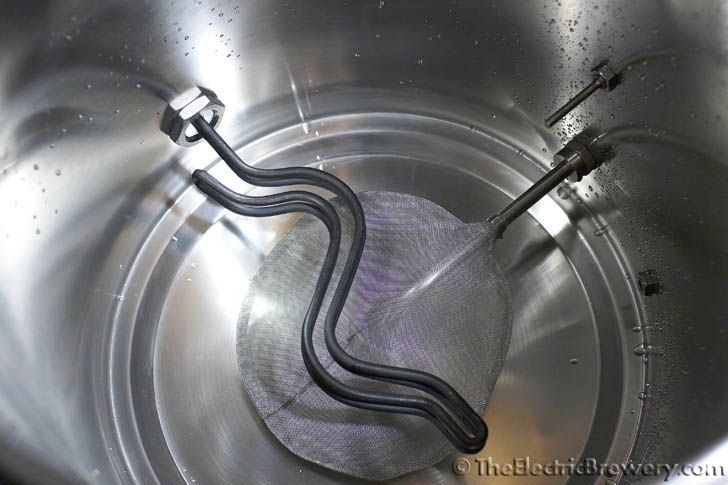
Heating element installed in the Hot Liquor Tank (for heating up the strike and sparge water):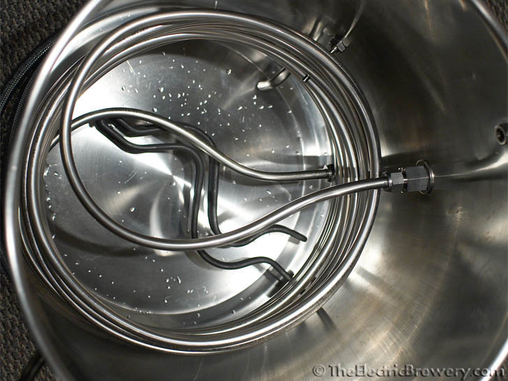
Outside view of the Hot Liquor Tank which shows the heating element covered up inside a waterproof metal box: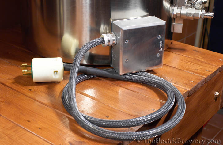
One of the most challenging things in creating our Electric Brewery was figuring out how to attach the heating elements to the Blichmann kettles in a safe and secure manner. You want the entire kettle to be electrically grounded for safety reasons, the same way any power tool or appliance chassis is grounded. Grounding means that the entire metal chassis (in this case the entire kettle) is connected to your house's electrical system ground plane. This ensure that any stray current can find its way to ground instead of through something else (such as the brewer!) in the off chance that something goes wrong and one of the 'hot' wires becomes disconnected and touches the kettle. Without proper grounding the kettle could become energized and pose a great danger. A proper electric brewing setup should always be properly grounded.
We also don't want any wires exposed as they could be easily damaged. Kettles are heavy and moving them around during cleanup provides plenty of opportunity for the brewer to inadvertently bump protruding parts against other things. No matter how careful you are, it will happen. We want the wires to be protected as much as possible and completely covered up.
The Blichmann Boilermaker kettles we use are all 100% weldless, meaning that there are no screw-on threaded fittings and none of the parts are welded on. We wanted to do the same with the heating elements. Some feel that weldless means you'll end up with poorly fitted, lose, or leaky connections. Not true. When done right weldless connections will be tight fitting, never leak or require any adjustments, and be perfectly safe. In the rest of this article we'll show you exactly how to do that.
You'll be installing heating elements in both the Boil Kettle and the Hot Liquor Tank. The method used to install the element in both is identical, so you'll have to repeat the instructions here twice (once for each kettle).
A note on rust: Previously we used the Camco #02963 5500W 240VAC ultra low watt density (ULWD) RIPP element which had proven to be very popular amongst home brewers with electric setups. Like most standard hot water heater elements this model has an iron base (not stainless steel) so it will rust if left in water for extended periods. Electric water heaters combat this by also having a sacrificial magnesium anode installed. The anode's sole purpose is to oxidize first, thereby protecting the heating element iron base from rusting. Brewing kettles do not have an anode so make sure you do not leave water in the kettle for a prolonged period of time if using a heating element with an iron base. This may be exacerbated if you have hard water. Some brewers will install a sacrificial magnesium anode in the side of their kettle to combat this issue if using a heating element with an iron base. See this forum thread for some example installations and instructions. Today we use the newer Camco #02965 (5500W) stainless steel heating element made specifically for beer brewing. An anode is not required.
Parts and tools
To purchase heating elements pre-assembled or all these parts in kit form see our products page.
The following parts are needed:
- (Qty: 2) RECOMMENDED: Camco #02965 5500W 240VAC ultra low watt density (ULWD) stainless steel RIPP element
- or -
(Qty: 2) Camco #02963 5500W 240VAC ultra low watt density (ULWD) RIPP element - (Qty: 2) Weatherproof 2-gang outlet box with at least one 3/4" NPT female access hole
- (Qty: 4) Weatherproof 2-gang blank cover and gasket
- (Qty: 8) #6-32 hex nut
- (Qty: 8) #6 locking washer
- (Qty: 1) Aerosol spray can of general purpose grey enamel primer (for priming metal)
- (Qty: 1) Aerosol spray can of hammered metal finish spray paint - silver colour (for painting metal)
- (20 feet) 300V 10 gauge, 3 conductor wire, oil/water resistant, rubber coating, rated for outdoor use
- (2 feet) Electrical tape
- (2 feet) 3/4" black heat shrink tubing
- (Qty: 6) 12-10 gauge ring terminal, #10 hole, yellow
- (20 feet) 1/2" expandable braided sleeving - carbon/black colour
- (Qty: 2) NEMA L6-30 (250VAC, 30A) twist lock electrical male plug
- (Qty: 1) JB Weld cold weld compound
- (Qty: 2) Silicone high temperature o-ring (1-3/16" ID, 1-7/16" OD, 1/8" thick, AS568A Dash No. 217, Durometer hardness A70, FDA compliant, -65F to +450F)
- (Qty: 1) Food grade silicone adhesive/sealant (-75F to +400F, Food grade: Meets MIL-A-46106B, Group I, Type I, FDA compliant, USDA approved, NSF 51 certified)
- (Qty: 2) Stainless steel washer/shim (1-1/2" ID, 2-1/4" OD, 0.075" thick)
- (Qty: 2) Standard straight cord/wire grip, 3/4" NPT
- (Qty: 2) Stainless steel locknut 1" NPS
You'll also need the following tools:
- GreenLee 1-1/4" round chassis or radio (not conduit/pipe) punch for making 1-1/4" diameter holes
- ~57mm (2-1/4") bi-metal hole saw for making ~57mm (2-1/4") diameter holes
- Drill press
- Hand drill
- Metal file
- Phillips #2 (crosshead) screwdriver
- GreenLee 36414 1-3/8" step drill bit
- 5/32" high speed metal drill bit
- Adjustable wrench with 2" jaw opening
- Water heater element wrench
- Cutting fluid
- Heat gun
- Sharpie permanent marker
- Wire cutter/stripper
- Double ratcheting wire crimper
- (Qty: 2) 3" Heavy duty C-clamp
Some sellers do not ship outside the USA. If you live outside the USA (like us), we recommend using a forwarding service such as Shipito. We've used them to ship to Canada. The good news is that shipping within the USA is very inexpensive or often free. You then simply pay a small forwarded fee plus the cost of whatever shipping method you choose (USPS, FedEx, etc). They will even consolidate multiple packages into one to save on shipping. We recommend USPS whenever possible to minimize brokerage fees.
STEP 1: Punch a 1-1/4" hole in the bottom cover
 We use a weatherproof 2-gang metal outlet box and two metal blank covers to cover up the connection end of the heating element. These heavy metal boxes and covers are meant for installing outlets or light switches in wet locations so there's no risk of water or any other liquid getting inside if you hose down the kettle or have a spill.
We use a 2-gang box (made for two switches or sets of outlets) to make installation simpler. You may find you have enough room in a single gang box, but odds are it'll be a bit tight.
Most industrial boxes and covers that are considered safe for wet locations should work as long as they're metal. We want a metal box to make it easy to ground the whole setup properly.
Two metal blank covers are needed as well: One for the outside and another that will be permanently epoxied to the bottom.
Weatherproof 2-gang metal outlet box and blank cover with foam gasket to provide a water resistant seal:
 The weatherproof outlet box is too thick and uneven to create a nice flat surface to seal up against the kettle, so we use one of the blank covers on the bottom of the outlet box. Drill a pilot hole using a hand drill first and then use the GreenLee 1-1/4" chassis/radio punch to create a nice round hole that is 1-1/4" in diameter. This hole will let the threads of the heating element pass through.
We don't recommend using hole saws or step bits to make this hole in the cover as you want it to be precise with nice clean edges. A punch like this slowly slices through the metal creating a perfect hole by drawing a circular cutting edge towards a flat edge.
Make sure to purchase a chassis (sometimes called radio) punch to make this hole. Conduit punches are also available but their punch size does not actually match the size of the hole they make (the punch size is actually the NPT (national pipe thread) pipe size) - just to make things confusing! When in doubt double check what size hole the punch will make before using it. The punch you want is the GreenLee 1-1/4" chassis/radio punch which makes a hole that is 1-1/4" (1.25") in diameter.
We'll be using the same punch again to make holes in the Blichmann kettles later in these instructions.
Center marked and measured with a Sharpie permanent marker:
Drill a pilot hole in the center with a hand drill and bit, and then install the GreenLee 1-1/4" chassis/radio punch as shown below. Turn the nut on the bottom of the punch to draw the upper cutting half towards the bottom, creating a perfectly round hole without any rough edges: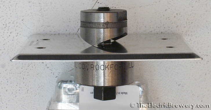
The finished hole:
Two photos showing how closely the heating element fits in the new hole (the black rubber washer that was included with the element will not be used):

STEP 2: Cut a 2-1/4" hole in the bottom of the conduit box
 Cut a 2-1/4" diameter hole in the middle of bottom of the 2-gang conduit box using the 2-1/4" bi-metal hole saw installed in a drill press.
The hole is larger than the previous 1-1/4" hole we punched in the cover as we want to leave enough room for the inside edge of the heating element.
A hand drill will work too, but a drill press is much faster and accurate, if you have one handy.
One of the best tools that we added to our workshop recently was a drill press - it makes cutting holes so much easier and more accurate than we could have ever imagined.
A drill press doesn't have to take up much space and many are available for considerably under $100. It'll come in extremely handy later on when we cut holes for our control panel.
Use a drill press and 2-1/4" bi-metal hole saw to cut a larger hole in the center of the 2-gang conduit box. 3” heavy-duty C-clamps hold the conduit box in place:

STEP 3: Attach the cover plate to the bottom of the conduit box
 We want to permanently attach the metal cover plate with the hole in it to the bottom of the 2-gang conduit box.
We'll be using small nuts, bolts, and locking washers to ensure the two parts are electrically connected and then use JB Weld (epoxy) to bond the two parts together permanently.
JB Weld forms a permanent bond that is as strong as steel. It's safe to use in heated environments up to 500F and is impervious to water, gasoline, chemicals, and acids (and beer). It's fantastic stuff!
File down the underside of the box so that that the cover will sit nice and flush. Using the cover plate screw holes as a guide, mark 4 holes on the box with a permanent marker and drill through:
Holes drilled. We're going to use the included machine screws, #6-32 hex nuts, and #6 locking washers to hold the cover on the bottom of the box along with some JB Weld:
Apply a bead of JB Weld around the 2-1/4" hole on the underside of the conduit box.
Sand around the hole on the underside of the cover:
Press the cover in place and remove to ensure that you've applied enough JB Weld to seal all around:
Screw down the cover using the included machine screws, #6-32 hex nuts, and #6 locking washers.
Clean away any excess JB Weld that oozes out. We want to keep the bare area of the cover clean.
Let the JB Weld dry overnight before continuing:
Some conduit boxes may have ground screws in different locations than shown in the pictures above, including near some of the holes we drilled for the machine screws to pass through. If this is the case with your conduit box, simply remove the ground screws (usually green) and file down the posts where they were attached (a Dremel rotary tool works well) to provide room for the machine screw, nut, and locking washer. In a later step we will be attaching the ground wire to one of these cover plate machine screws instead. Where the ground wire attaches is not critical. It simply needs to be properly grounded to the box chassis.
A ground post that must be removed/filed down:
To better match the stainless kettles, the box was primed with a general purpose grey enamel spray primer (shown below) and then spray painted with silver Rust-Oleum hammered metal finish (not shown - see finished photos further below) to give it a metallic finish. Any kind of primer and paint meant for metal will work.

STEP 4: Punch a hole in the kettle
Now comes the fun part: Putting a hole in your nice shiny new Blichmann Boilermaker kettle! We use the same GreenLee 1-1/4" chassis/radio punch to create a nice round hole that is 1-1/4" in diameter. This hole will let the threads of the heating element pass through.
As mentioned previously, make sure to purchase a chassis (sometimes called radio) punch to make this hole. Conduit punches are also available but their punch size does not actually match the size of the hole they make (the punch size is actually the NPT (national pipe thread) pipe size). When in doubt double check what size hole the punch will make before using it. The punch you want is the GreenLee 1-1/4" chassis/radio punch which makes a hole that is 1-1/4" (1.25") in diameter.
Decide how you want the heating element positioned inside the kettle. We suggest either to the left or right of the kettle (with the valve in front) and as low as possible. Keep in mind the conduit box that has to be positioned on the outside as it will limit how low you can install the heating element. If you place the heating element too high you may not be able to brew very small batches of beer as the element should always be 100% submersed when heating.
Don't rush this step. Think carefully about where you want the element installed. The last thing you want to do is punch a hole in the kettle and then later decide that it should have gone somewhere else.
In our Boil Kettle (BK) the center of the element is 4" from the bottom and on the right side. In our Hot Liquor Tank (HLT) the center of the element is 3" from the bottom and on the left side. The Boil Kettle element is installed slightly higher than the one in the Hot liquor tank as we have a large hop strainer installed in the boil kettle which sits on the bottom so the element could not be installed any lower. This places the element just below the 5 gallon marker in the boil kettle so 5 gallons is the minimum volume of beer we can produce with this setup. We typically brew 10-13 gallons.
We chose to install the heating elements on opposite sides of the kettles to keep the electrical boxes out of the way as seen in the photo below. In the end it would not have mattered on which sides we installed the elements.
Our kettles with heating elements installed.
The Boil Kettle (BK) is used to boil wort, the Hot Liquor Tank (HLT) is used to heat strike and sparge water: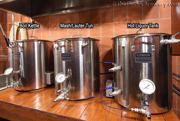
Mark the location where the heating element will be installed in the kettle with a Sharpie permanent marker:
Use the GreenLee 36414 1-3/8" step drill bit to drill a pilot hole in the kettle. Avoid cheap knockoff step drill bits as they simply don't last and end up costing you more in the end. Make sure to apply a few drops of cutting fluid first to prevent the bit from heating up. Hint: Use a hammer and a small nail to create a small dent first. This will prevent your step bit from jumping around and scratching up the nice new kettle:

A close-up of the pilot hole from the inside (see below). Even when used carefully a step bit will make quite a mess of the metal. This is why we don't recommend using regular bits, step bits, or hole saws to make precision holes. They will not be precise. They're only useful for making the initial pilot hole as we've done here.
Separate the GreenLee 1-1/4" chassis punch and place half on the inside and half on the outside of the kettle:

Using a wrench, turn the bolt on the punch to cut the hole in the kettle:
As the two halves are pulled together, the punch cutting edge easily cuts through the 18 gauge (1.2mm thick) wall:
Done! One perfectly round & clean hole with minimal effort:
STEP 5: Secure the heating element
 The Camco #02965 5500W heating element is held in place by a large 1" NPS stainless steel lock nut inside the kettle.
To seal the kettle from the outside, we use the same trick that Blichmann uses on these kettles to seal all of their weldless fittings: A high temperature food grade silicone o-ring is placed inside a metal washer/shim to make the seal. The washer ensures that we don't overly compress the o-ring and cause it to bulge and leak when we tighten the large nut inside the kettle. It also ensures that there's a tight fit between the electrical box and the kettle: Without the washer the box would be resting against the o-ring and would move around if it were pushed/pulled. The black rubber washer that was included with the heating element is not used.
Just like Blichmann's weldless fittings, the size of the o-ring and washer were selected so that you'll be able to tighten everything down completely and the electrical box won't move at all.
Remove the rubber washer and then carefully feed the heating element through the hole in the conduit box. Place the high temperature silicone o-ring (1-3/16" ID, 1-7/16" OD, 1/8" thick, AS568A Dash No. 217) and stainless steel washer/shim (1-1/2" ID, 2-1/4" OD, 0.075" thick) around the element threads:

Carefully feed the heating element through the hole in the kettle:
Screw on and tighten the 1" NPS stainless steel lock nut on the inside of the kettle using a regular 2" wrench while using a water heater element wrench on the outside to stop it from turning. Tighten this down until the box on the outside is completely tight:

The outlet box on the outside should now be pressed up against the kettle and unable to move or spin. The washer between the box and the kettle ensures that the o-ring did not bulge or get overly compressed. While it looks like there may be 2-3 washers in the photo below, there's actually only one. You're seeing reflections off the box cover and the kettle:
A cut-away view of how it all works:
The high temperature food-grade silicone o-ring creates the waterproof seal between the kettle and the electrical box in the same way that Blichmann does with their weldless attachments (sight gauge, thermometer, and 1/2" valve) on their Boilermaker kettles. The black rubber washer that was included with the heating element is not used.
When compressed slightly after installation, the o-ring presses against the heating element to seal off the inside of the kettle from the inside of the electrical box. The last thing we want is hot liquid from the kettle to seep into the outlet box. To test this lateral seal, we boiled ~10 gallons of water for about an hour with the outside electrical box cover removed. No matter how we pushed, pulled, or tried to turn the electrical box, we were unable to create any leaks.
Just to be on the safe side however, we use food grade silicone adhesive on the inside of the outlet box around the heating element. This provides an additional safeguard against any possible leaks:
STEP 6: Electrical connections
Time to attach cables to the heating elements so that we can actually plug them in!
The first step is choosing the wire to use for our setup. Electrical wire is rated for current and voltage. The larger the diameter the wire, the more current it can carry, so to figure out the wire size (called 'gauge') we only need to need to know how much current the wire will be carrying. Figuring our current is simple using Ohms law as we know the elements are 5500W and that they use 240 volts AC:
Current = Power / Voltage = 5500 watts / 240 VAC = 22.9 Amps
Our elements will draw 22.9 Amps. The proper size electrical wire for 22.9 amps is 10 gauge or lower (i.e. bigger) as (generally speaking) 10 gauge wire is used in circuits that carry up to 30 amps in household use. The voltage rating of the wire should be 240V or higher. 300V and 600V are common ratings found on electrical wiring. This is the sort of wiring you'd see used on a household clothes dryer as dryers use 240 VAC / 30 Amp outlets.
We use a 10 gauge wire with 3 separate conductors, called "10/3" wire: Two conductor carry each of the 120 VAC "hot" lines to produce the 240 VAC the element uses, while the third will be used as a ground. It's important that everything be grounded for safety reasons: Having the kettle grounded ensures that the current will pass to ground immediately and trip your circuit breaker or fuse instead of passing somewhere else (like through the person brewing!) if one of the hot lines was to be become disconnected and touch a kettle.
 Look for cables that are oil/water resistant with a rubber coating and rated for outdoor use. Use whatever length is needed between the kettle and the control panel. 10 feet is fairly common but don't be afraid to use a bit more, just in case. The last thing you want is a cable that's too short.
We wrapped the wire in 1/2" expandable braided sleeving and used about 6" of 3/4" heat shrink tubing at the plug ends to help ensure that the braided sleeving did not fray. While not required, it gives the wire a nice finished look and helps protect it.
Slide the expandable sleeving on first followed by the shrink wrap tubing. Apply heat using a heat gun to shrink the tubing.
Carol brand 10/3 wire rated for 300V. CSA / UL approved and water resistant:
We wrapped the 10/3 wire in 1/2" diameter carbon/black colour expandable braided sleeve.
The last six inches are wrapped in 3/4" heat shrink tubing to keep the expandable sleeve in place: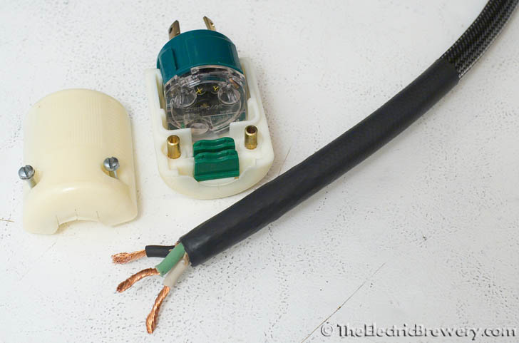
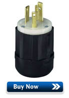 There are many options available for the electrical plug. We chose to use turn-lock or 'locking' plugs as they plug in like any normal plug but then are turned slightly to lock them in place to prevent accidental disconnection.
Just like the electrical wire, we need to use 3-prong plugs rated for both 30 Amps and 300V at an absolute minimum in our setup with 5500W/240VAC elements.
The most common NEMA style plug that meets our requirements is called a NEMA "L6-30" plug, rated for 250 VAC and 30 Amps.
(The observant reader will note that we actually used NEMA L9-30 plugs (rated 600 VAC instead of 250 VAC) as these higher voltage plugs were more readily available at the time we assembled our brewery. You may always use a plug or connector rated higher in voltage or current than required).
The GREEN ground wire is connected to the ground blade, while the black and white (hot wires) are connected to the other two blades. Normally in AC circuits BLACK signifies a hot wire while WHITE is NEUTRAL, but in our setup both BLACK and WHITE are used as 120 VAC hot wires so the orientation of BLACK and WHITE does not matter here.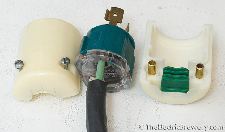
Make sure your wire is held tightly by the plug crimp/strain relief (the green tab at the right side of the above photo). Many plugs have reversible strain reliefs depending on the size of the wire used so make sure to check the documentation. The cord should be held in place tightly by the plug such that strain isn't placed on the wire screw connectors.
The finished wire with plug, heat shrink tubing, and expandable sleeving installed: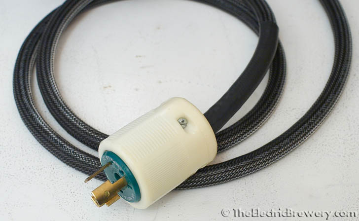
The other end of the wire is going to connect to the electrical box attached to the element in the kettle. To avoid the expandable sleeving from fraying we wrapped the last few inches of it with electrical tape. Leave enough room for the three conductors to move inside the electrical box: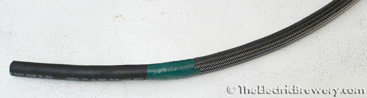
We use a 3/4" NPT cord/wire grip to hold the wire in place at the outlet box.
The grip holds the wire firmly in place and stops the wire from moving.
Once the grip cover is screwed on the rubber seal creates a water resistant seal from the outside: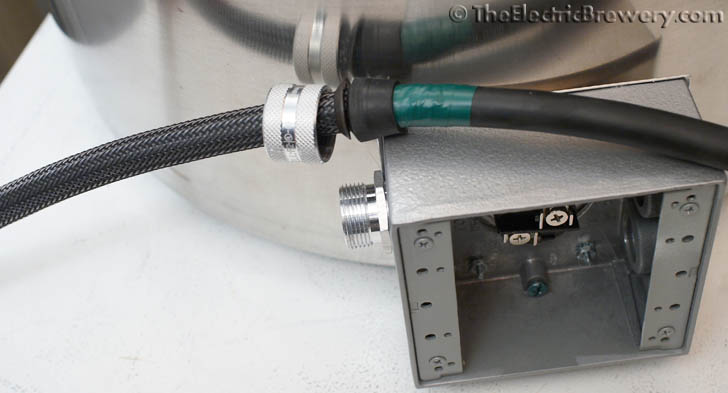
Before tightening the grip cover make sure you have enough free wire to connect to the two element screws and the outlet box ground screw: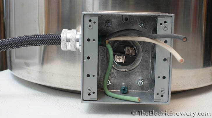
We use 10 AWG ring compression terminals to connect all 3 conductors: The BLACK and WHITE hot wires connect to the element screws (the orientation does not matter), while the GREEN ground wire connects to the electrical box. The picture below shows two of the three wires connected: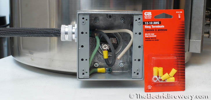
If you have a multimeter handy you can do a safety check of the ground: Measure the continuity between the stainless kettle and the ground spade on the electrical plug. It should measure as a short (close to zero ohms). Proof that your kettle will be properly grounded.
Install the electrical box cover. Making sure to use the included foam gasket to create a water resistant seal: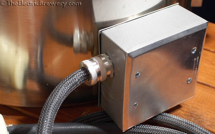
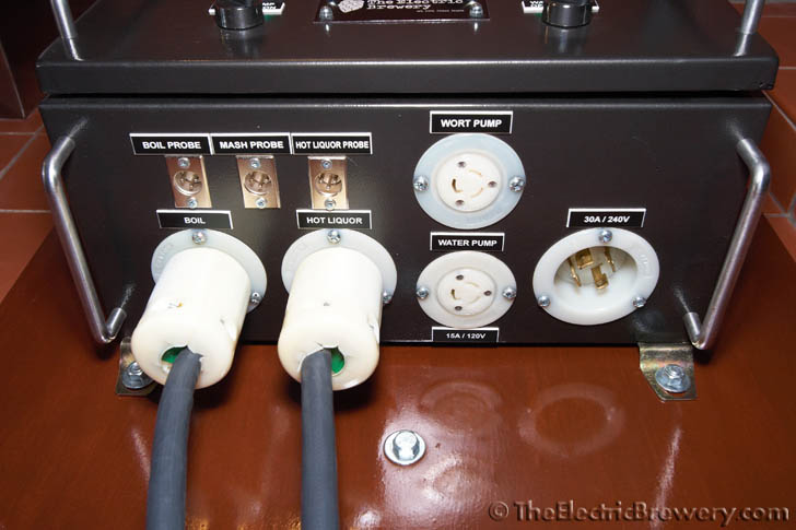
The locking plugs connect to the receptacles labelled BOIL and HOT LIQUOR on our control panel: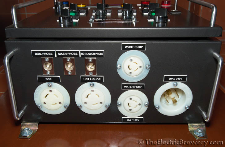
That's it! Enjoy your new weldless, safe, and water resistant electrical Blichmann Boilermaker kettles.
Continue on to Building Your Brewery - Temperature Probes.


