Search
Complete Guide to Building Your Brewery

$19.95 USD

Support our site by using these affiliate links
Mash/Lauter Tun
STEP 1: Add the input ball valve
 The sweet wort is recirculated by a pump through the HERMS coil in the Hot Liquor Tank to compensate for heat loss that occurs over time while the grain is mashed. We set the control panel to the desired mash temperature and the temperature of the sweet wort is maintained for as long as required.
The sweet wort exits out the dip tube and ball valve at the bottom of the Mash/Lauter Tun. This dip tube and ball valve came with the kettle so there is no need to add them. What we need to add now is a way for the sweet wort to return to the kettle.
This same ball valve will also be used to bring sparge water into the Mash/Lauter Tun.
Mash/Lauter Tun input quick disconnect with ball valve: 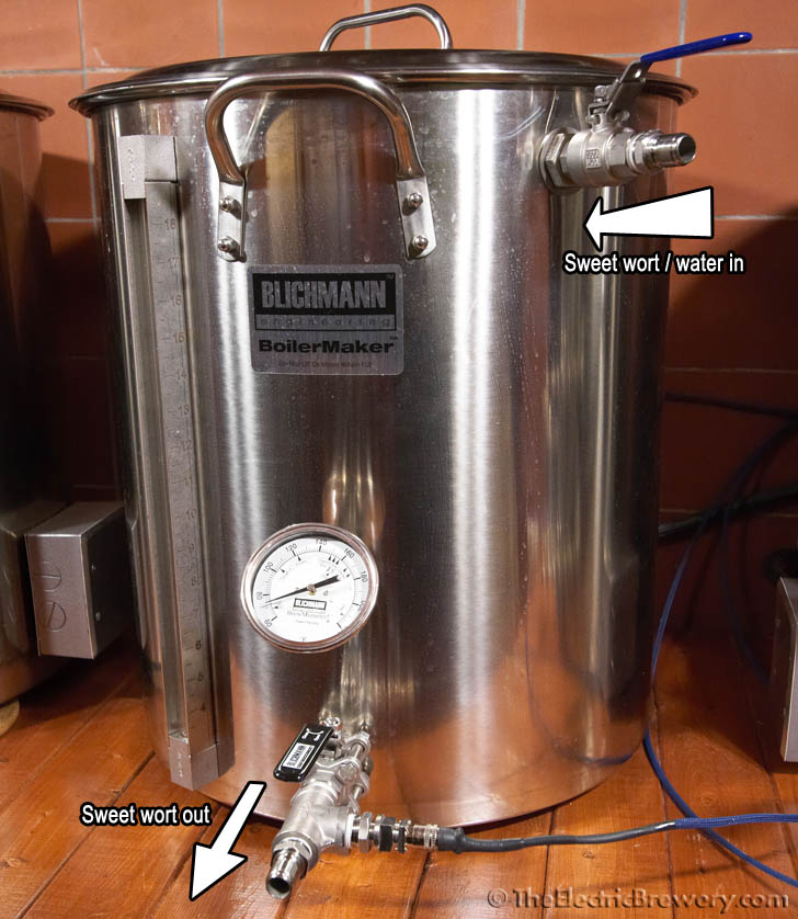
The parts outside the kettle for the input are identical to what we used previously on the Hot Liquor Tank.
The parts inside are different as we use a silicone hose: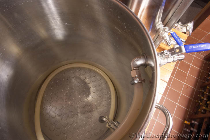
 We use a high temperature silicone food-grade return hose (1/2" ID, 7/8" OD) that simply rests on top of the grain bed. The silicone tubing we use is odourless, tasteless, inert, and FDA food-grade approved from -100F all the way up to 500F. The tubing is also translucent which lets us see the flow of liquid and air bubbles. This is high quality completely inert tubing, it's the same sort of stuff that's used in pharmaceutical labs and dairy farms.
The 5 foot length ensures that we can brew any batch size regardless of how much grain is used. When it comes time to sparge (rinsing the sugars out of the grain with water) we simply start pumping sparge water to the top of the grain bed using the same hose. The hose is not moved. The sparge water is pumped through the HERMS coil effectively cleaning the coil of any sweet wort.
If you frequent other brewing websites you'll notice that there are countless methods for delivering sweet wort and sparge water to the top of the grain bed such as perforated manifolds and rotating arms. We find these an unnecessary complication that require extra work, extra cleaning, and may clog due to the small holes if some grain is inadvertently circulated. Permanently installed devices will also get in the way, making cleaning the MLT more difficult. Special rotating sparge arms cannot be used during the mash recirculation as the introduction of oxygen to the sweet wort by splashing needs to be minimized, so extra steps are required to add/remove these devices between the time the mash is complete and sparging begins.
Brewers argue that without these special perforated manifolds or rotating arms that channelling will occur. Channelling occurs when the sparge water used to rinse the grains does not pass through the grain bed evenly and leaves sugars behind, reducing the systems efficiency. In an ideal setup the sparge water will pass through the grain bed evenly from top to bottom, rinsing the sugar off every last bit of grain. In poorly designed setups, the liquid will create 'channels' from the top of the grain bed to the bottom. This typically happens when the liquid must pass through a smaller area at the bottom of the kettle such as a mesh hose. In our setup, the large perforated false bottom helps ensure that the sparge water passes evenly through the entire grain bed from top to bottom, washing all the sugar out in a piston like manner. Our setup repeatedly achieves high efficiency even though we 'only' use this simple piece of silicone hose for mash recirculation and sparging. Due to the simplicity of this setup, clogging is not possible and there are no extra parts to clean or to get in the way when you clean the kettle. Simpler is better!
Still not convinced? We admit those rotating sparge arms look pretty cool in action. Consider this: Sabco (makers of the Brew-Magic gas powered brewing systems) also use a simple silicone hose like ours for recirculating and sparging. They've sold hundreds if not thousands of their smaller multi-thousand dollar gas setups worldwide. If a $50 rotating sparge arm worked better we assume that they would be using it. Blichmann Engineering (the manufacturer of our BoilerMaker kettles) sells an optional sparge arm called the 'Auto Sparge'. It also uses a piece of silicone hose to recirculate and sparge in a manner similar to our setup.
The Blichmann 'Auto Sparge' arm also includes a valve and floating ball that stops/starts the delivery of sparge water as required to ensure that the rate of flow into the Mash/Lauter Tun matches that leaving the Hot Liquor Tank . While an interesting concept, we find that matching rates is very easy to do by hand using our two pumps. Keeping the setup simple results in no chance of clogs and less parts to clean.
The return hose simply rests on top of the grain bed. During mashing, sweet wort is recirculated.
When sparging, hot water is pumped to the top of the grain bed using the same hose in the same position.
 Just like the water input ball valve on our HLT, the center of the input ball valve on our MLT is also approximately 2" from the top of the kettle and approximately 4" from the handle. Once you've marked your location for the hole, use a GreenLee 13/16" punch to create a 13/16" diameter hole for the ball valve. Refer to Step 4: Punch a hole in the kettle from the Heating Elements section for instructions on how to properly create clean holes using a punch like this. Do not use step bits or drills bits exclusively as they do not create nice clean holes.
Like in previous instructions, wrap all threaded ends first with PTFE white teflon thread sealant tape to ensure a tight, leak-free fit. Then attach the ball valve and associated hardware to the inside/outside of the kettle as shown in the pictures below. Again, be careful to place the lock nut (part C) with the inner groove towards the kettle wall. The silicone o-ring (part D) will partially sit inside this groove to avoid being overly compressed between the lock nut and the kettle wall.
Breakdown of the MLT input ball valve connections:
(A) Stainless steel male quick disconnect 1/2" NPT male
(B) Stainless steel ball valve 1/2" full port
(C) Stainless steel 1/2" NPT lock nut
(D) Silicone high temperature o-ring (13/16" ID, 1-1/16" OD, 1/8" thick)
(E) Stainless steel nipple threaded 1/2" x close NPT
(F) Stainless steel washer/shim (1-1/8" ID, 1-5/8" OD, 0.062" thick)
(G) Stainless steel washer/shim (7/8" ID, 1-3/8" OD, 0.062" thick)
(H) Stainless steel street elbow 1/2" NPT female x 1/2" NPT male
(I) Stainless steel 1/2" NPT female x 1/2" barb fitting
(J) Stainless steel smooth-band worm-drive hose clamp (5/8" to 1-1/16" clamp diameter range)
(K) 5 foot piece of high temperature food-grade silicone tubing (1/2" ID 3/4-7/8" OD)


Tighten using a wrench until the whole assembly is firmly attached to the kettle wall. Tighten the hose clamp using a screwdriver until it is very snug and firm (cannot be pulled off). While the special smooth-band hose clamp we use is specifically designed for silicone hoses, when tightening making sure not to overtighten and damage the hose.
We do not recommend using regular hose clamps for silicone hoses as the band can cut into the hose when tightening and over time as the hose is moved. The special smooth-band hose clamps we use have a smooth band with rolled edges ideal for use with silicone hoses.


