Search
Complete Guide to Building Your Brewery

$19.95 USD

Support our site by using these affiliate links
Control Panel (Safe start interlock)
STEP 2: Wire up relay
Refer to the wiring basics section of the Control Panel (Part 2) instructions for some hints and tips on how to properly install spade terminals, self-adhesive tie mounts, and nylon ties.
When you previously purchased the various selector switches, they most likely came with both a normally open (NO) and a normally closed (NC) contactor. Up until now we have not used the NC contactors. We will be wiring up the two NC contactors on the pump switches and adding two NC contactors to the ELEMENT SELECT switch. These two new NC contactors are screwed into the backs of the existing NO contactors (see picture further below). Use two of the NC contactors from any of the other switches (other than the pump switches of course).
Wire up the components as shown in the diagram below using the wire sizes and colours indicated.
 Some hints:
- White (NEUTRAL) wires are shown as blue in the diagram.
- When orientation is not important, it is not shown. For example, it does not matter which side of NC contactors are wired as they are simply switches and switches do not have polarity.
- The POWER KEY switch was previously wired directly to the POWER IN RELAY coil. This wire must be removed otherwise the interlock feature will be bypassed and the control panel will power up regardless of how the three other switches are set.
- Previously the WORT PUMP and WATER PUMP switches only had their normally open (NO) contactor wired up. We are now adding a normally closed (NC) contactor beside the existing contactor. Only the new wiring is shown here. The existing wiring does not change.
- Previously the ELEMENT SELECT switch contained two normally open (NO) contactor that were wired up. We are now adding two normally closed (NC) contactors on top of the existing contactors. Only the new wiring is shown here. The existing wiring does not change.
Safe start interlock wiring diagram: 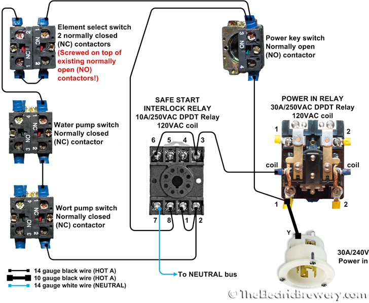
How it works
The safe start interlock relay only receives power when the POWER KEY switch is set to ON and all three other switches are set to OFF. Once the interlock relay receives power and latches, it feeds into the POWER IN RELAY coil to turn on the rest of the control panel. Once latched, power for the interlock relay is then also drawn directly from the POWER KEY switch through one of the poles in the interlock relay that is now closed. This keeps the interlock relay coil energized and allows the other three switches to be turned ON or OFF as required without turning off the control panel while in use or affecting the interlock capability. If power to the panel is cut, the interlock relay releases and the three switches must be set to OFF before the panel may be powered on again.
Our interlock relay has a test LED that will light up when the relay is closed. A red pushbutton on the front of the relay can be used to temporarily switch the relay manually. Neither of these is overly useful in our application, but many relays now include these features.
Location of the components:
Close-up of the relay and pump switches:
The ELEMENT SELECT switch with two NC contactors (right) on top of the existing NO contactors (left):
Done!
To test your new safe start interlock turn the control panel off and unplug the element and pump plugs from the bottom of the control panel (just in case). Set either or both of the pump switches to ON and/or the ELEMENT SELECT switch to BOIL or HLT and then turn on the POWER KEY switch. You'll notice that the control panel does not power up. The pump and element switches must all be set to OFF before the control panel will power up. You'll also note that if you turn off the control panel or lose power when any of the three switches are in the ON position, you will not be able to turn the panel back on until all three switches are first turned OFF.
While not an absolute requirement, this safe start interlock adds a little piece of mind and safety to our control panel for very little effort or cost. Brew safe!
Continue on to Building Your Brewery - Control Panel (Setup).
- « first
- ‹ previous
- 1
- 2
- 3
- 4


